Insulated van interiors
One design and manufacturing strategy. Sixteen vehicle models.
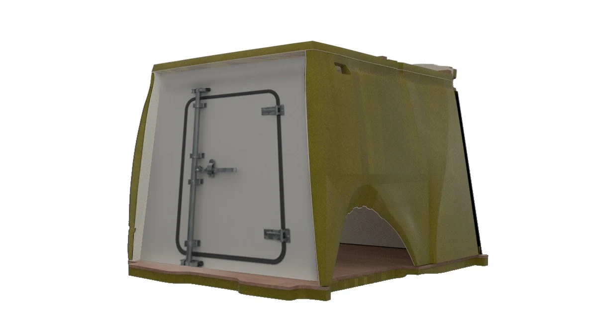
I led development, 3D modelling and CAD/CAM preparation, coordinated requirements with production and created drawings and work instructions.
A system developed for 16 van models, with parts adapted to the geometry of each vehicle body.
Designing how the product is made.
The craft-based process required much of the work to be resolved inside each vehicle. Development moved those decisions into the panels: defining geometries, preparing machining and planning the assembly sequence in advance.
Bringing an existing CNC machine into the process connected the digital model with component preparation.
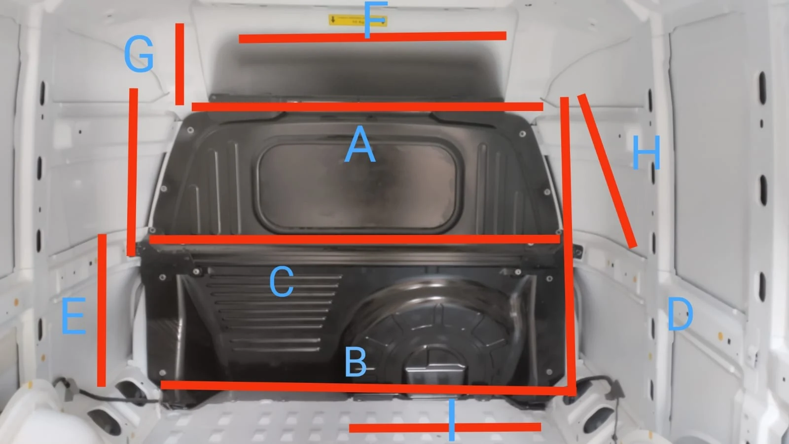
Form and sequence are designed together.
Floor, bulkhead, roof, side panels and doors form the enclosure. The order in which each part enters the vehicle is part of the design.
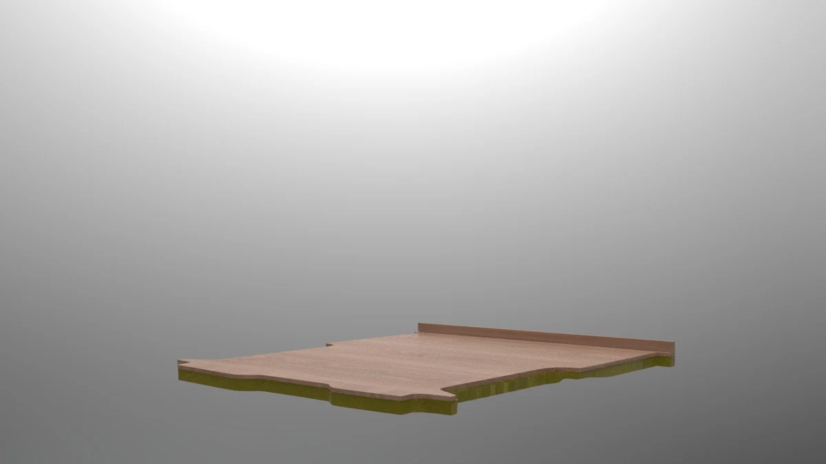
The base of the assembly.
The floor follows the vehicle geometry and establishes the base for the remaining panels.
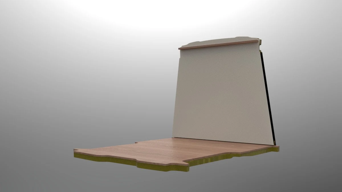
Completing the front enclosure.
The front panel separates the load space from the cab and is positioned on the base.
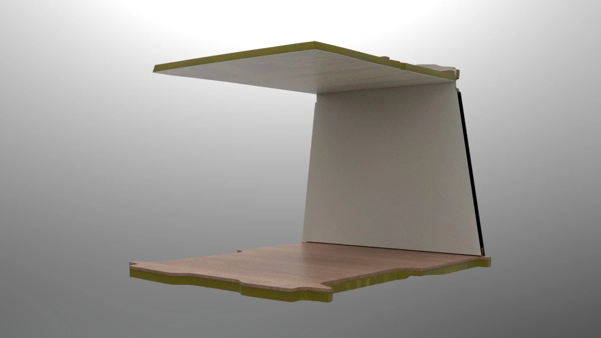
The roof goes in before the sides.
This order keeps enough space to bring the roof inside. Installing the side panels first would prevent that movement.
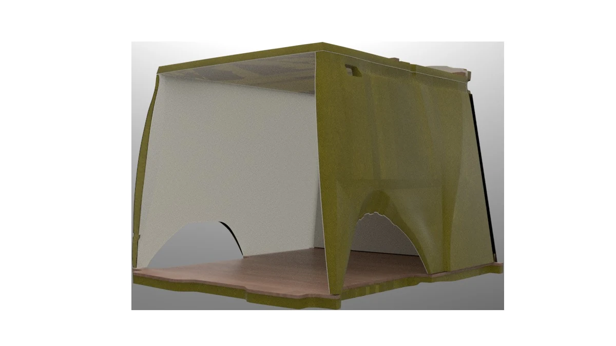
Closing the enclosure.
The side panels accommodate the wheel arches and meet the floor, roof and bulkhead.
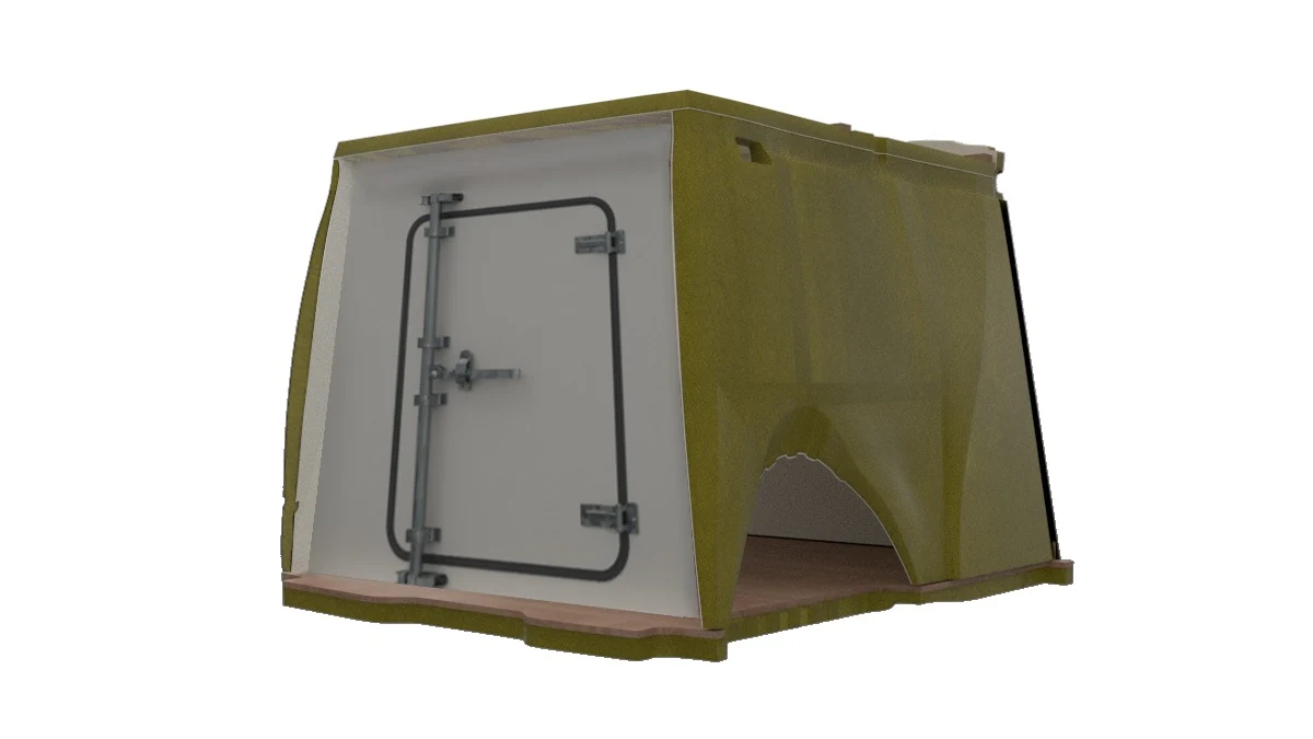
Resolving access.
The doors complete the assembly, followed by sealing and finishing work.
The sequence simplified joint sealing and avoided fibreglass reinforcement along every seam. Fibreglass was retained on the floor and doors.
A shared approach. Vehicle-specific solutions.
Each vehicle body required different contours, dimensions and interfaces. The side-access configuration also changed the panel and its finishing parts.
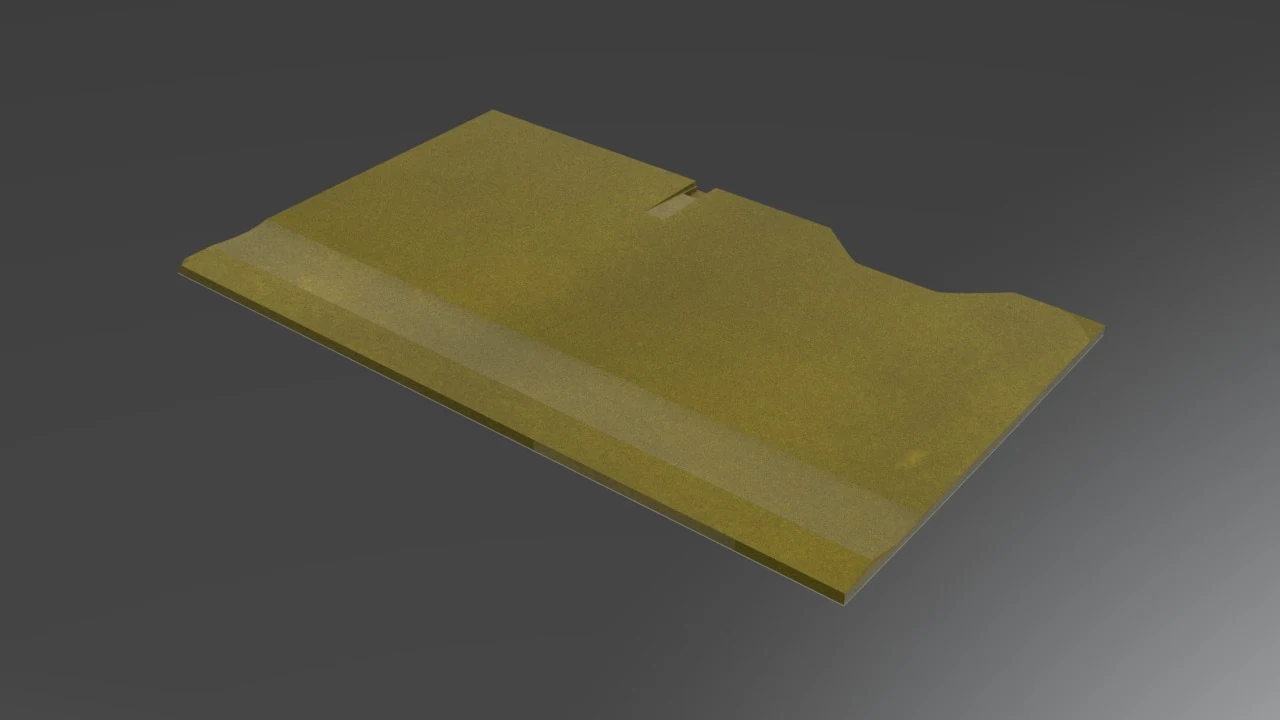
Closed side
A continuous enclosure adapted to the vehicle body.
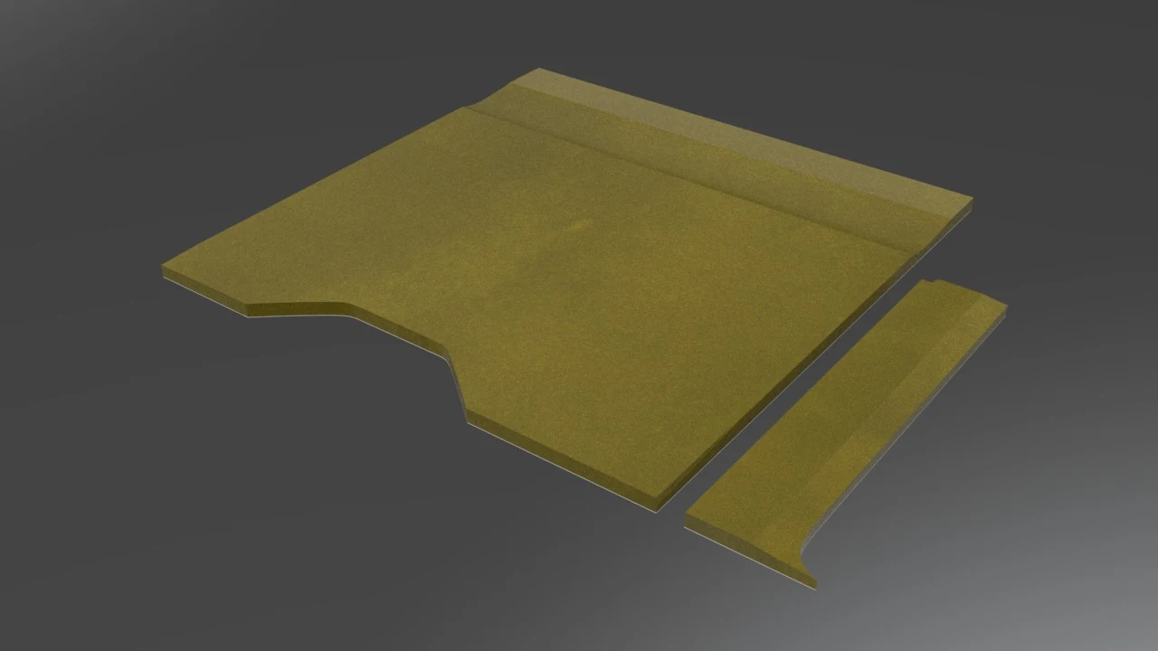
Side access
Panel geometry and trim that preserve the opening.
For frozen-food applications, pine reinforcements supported the refrigeration unit. The workshop team determined their construction to match the specifications and mounting points of the unit supplied by each customer.
From digital model to workshop.
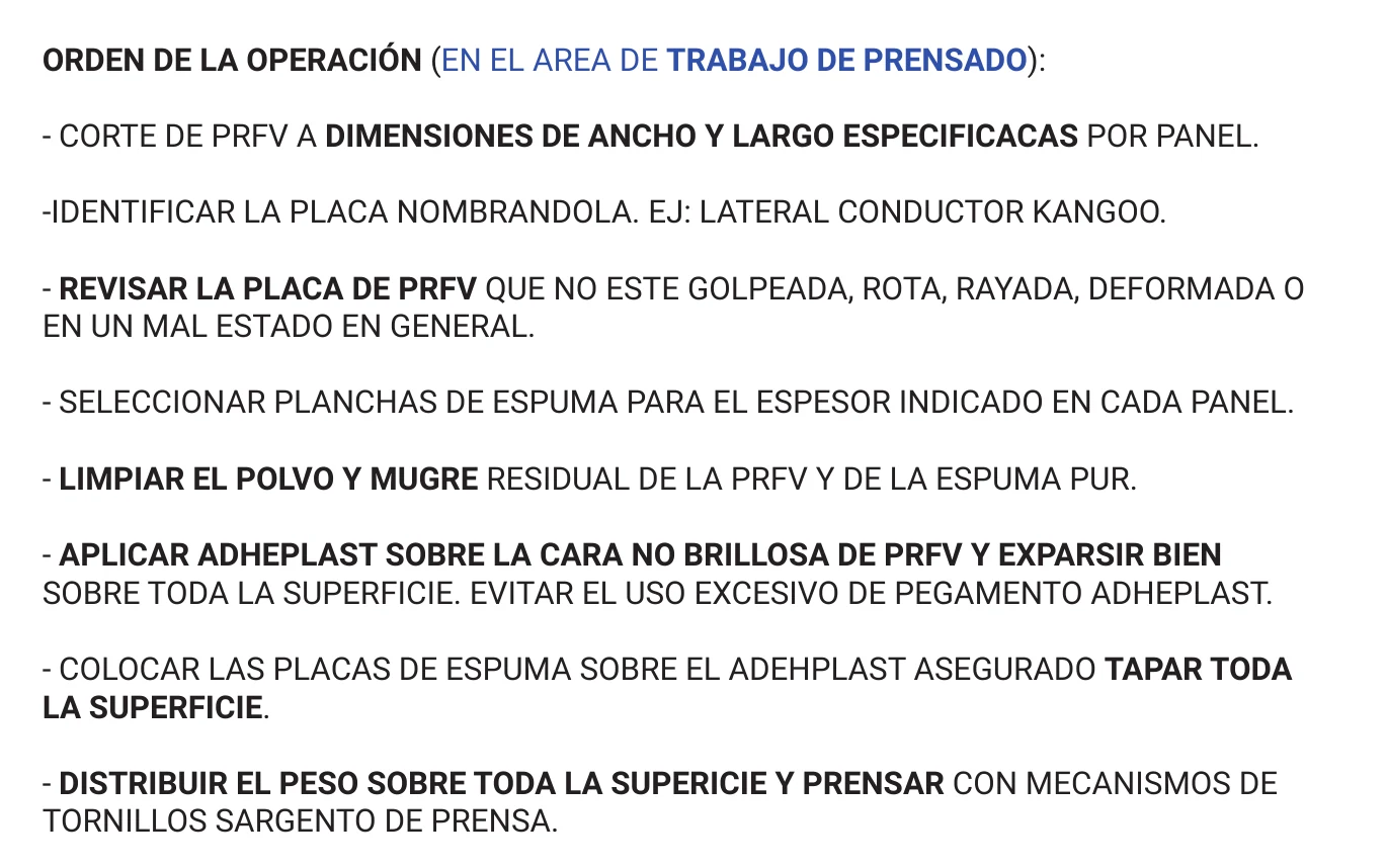
Drawings define the parts; CAM preparation translates their geometry into CNC machining. Manufacturing instructions organise plate identification, preparation and pressing.
The manuals also addressed task dependencies: completing interior work before applying fibreglass to the floor, and progressing with independent operations during curing.
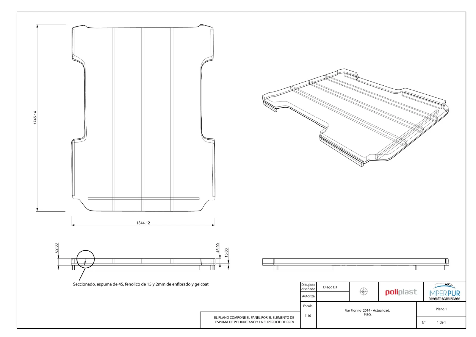
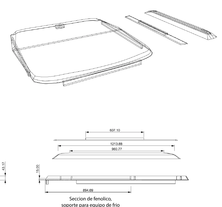
The development reached production.
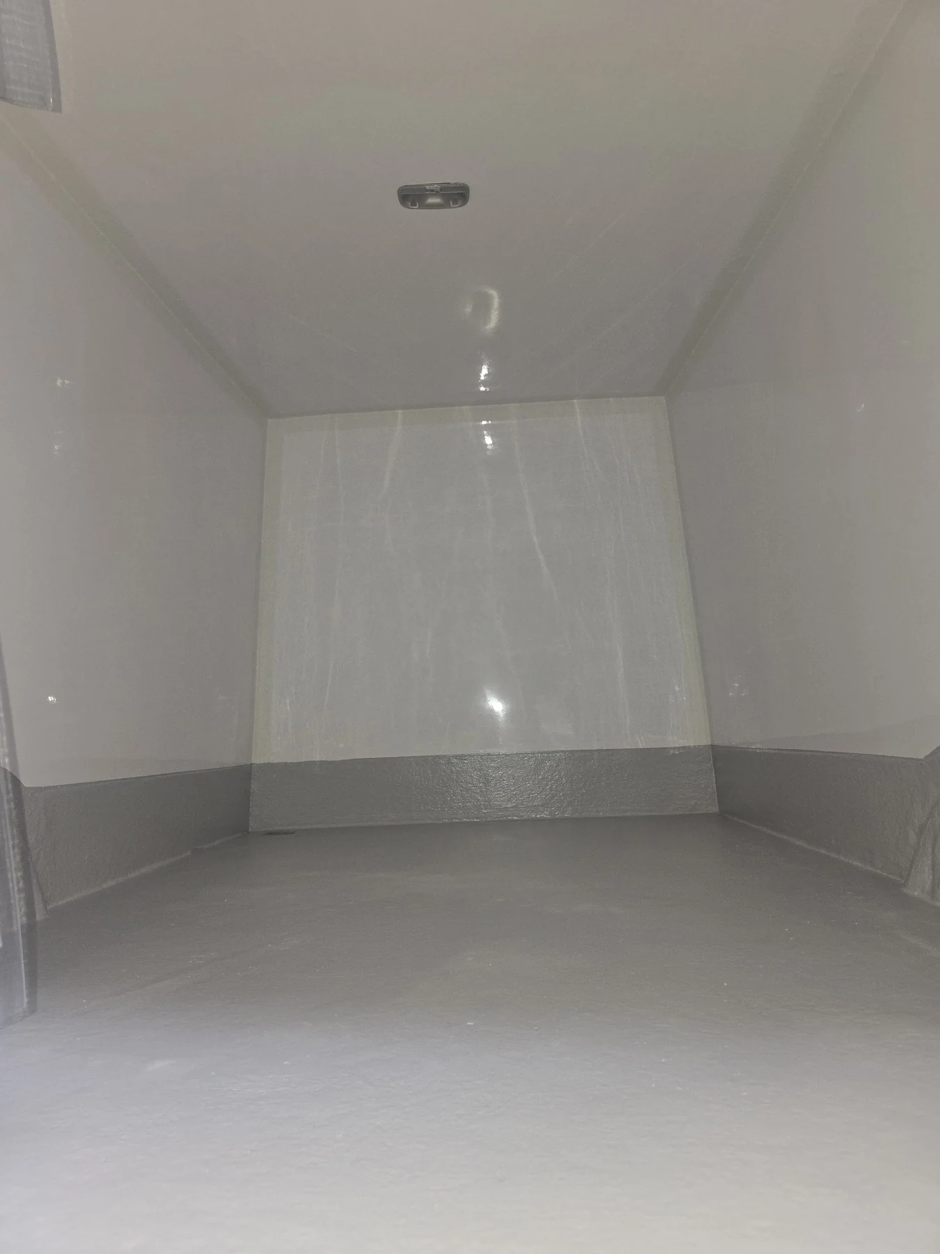
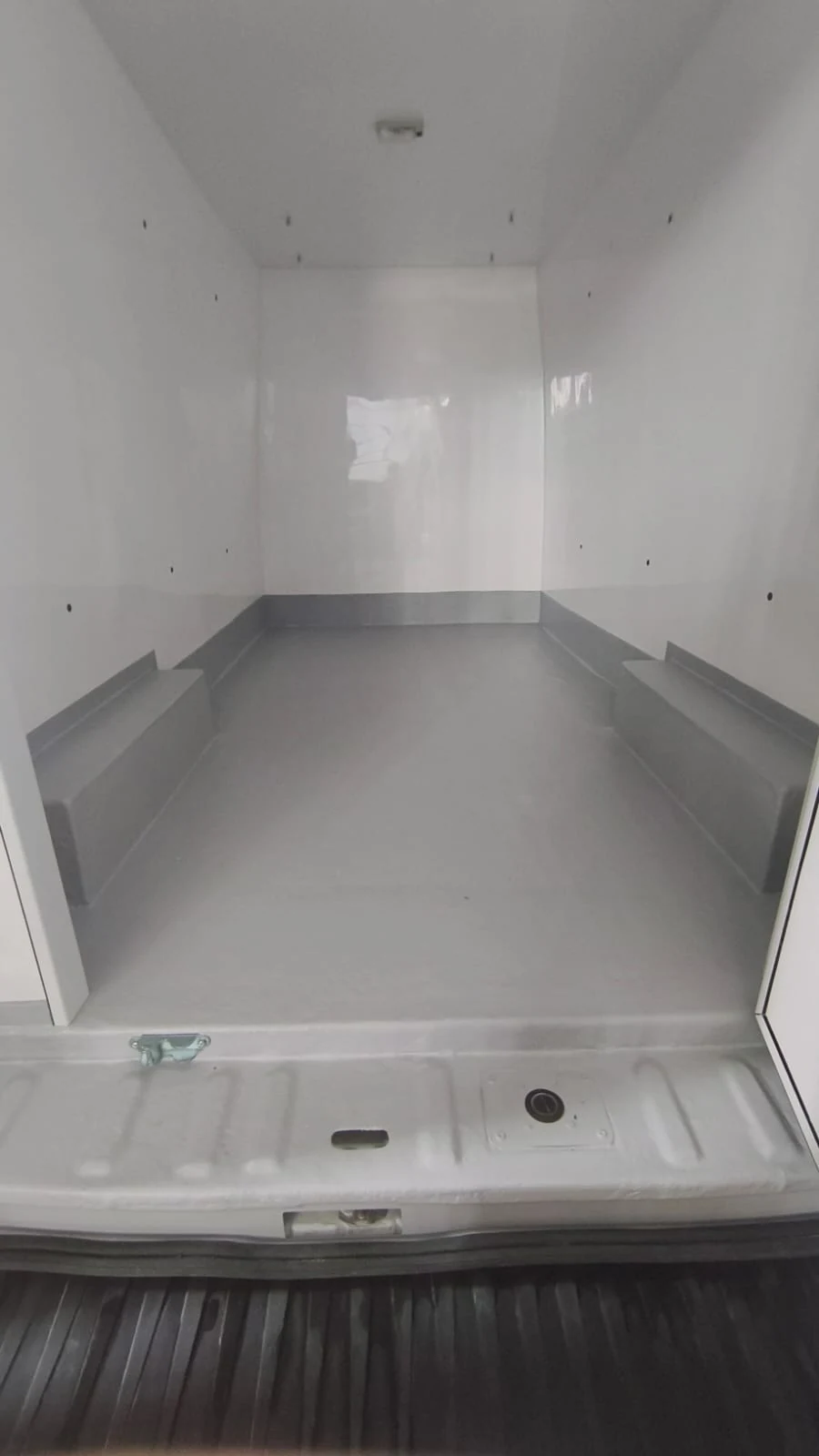
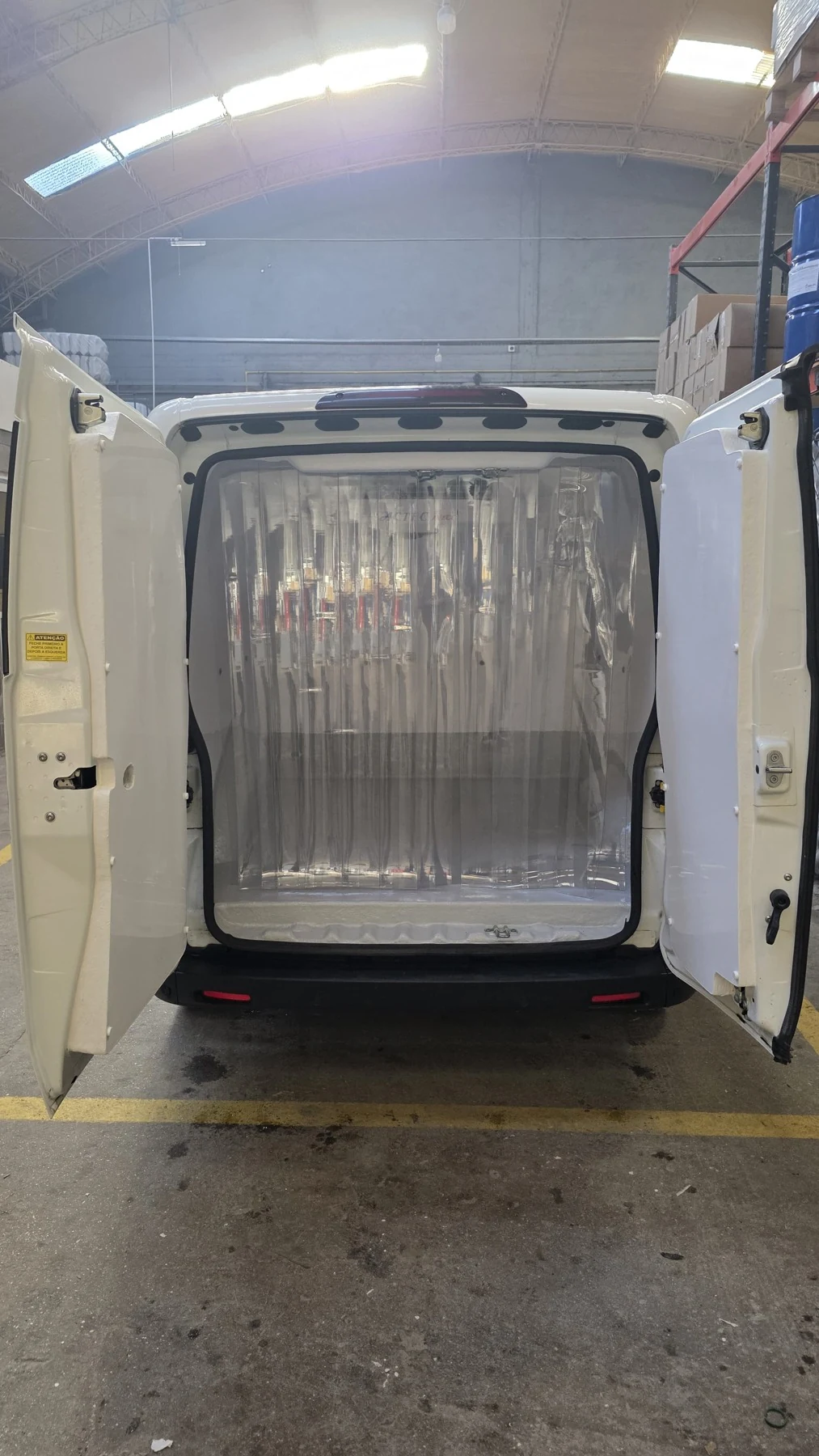
Interior surfaces, wheel arches, interfaces, access points and finishes were resolved as parts of one assembly. These examples represent work across 16 vehicle models.
More definition upfront. A shorter cycle.
Estimated complete cycle for Fiorino, from vehicle arrival to completion. Ranges based on production experience.
The improvement covers the full process: plate preparation, CNC machining, assembly, sealing, fibreglass work, doors and cleaning.
The workflow combined a CNC operator, a main assembler and occasional assistance for large panels.